
Automation
A retrofit concept for an existing CG optical machining station combines workpiece transfer with updated operator controls.
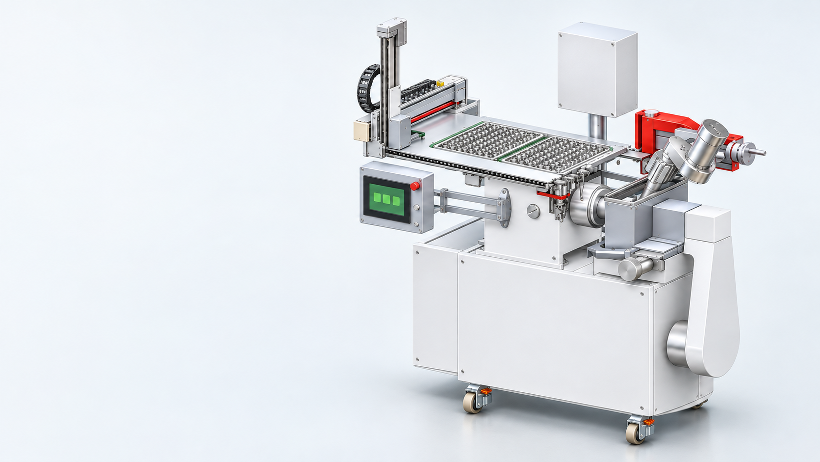
Linking the steps before
and after machining.
A part is picked from a tray, checked for orientation and transferred to the machining position. How these repetitive tasks can be automated depends on the existing machine.
These renderings are based on design sketches. The workpiece, machine and installation conditions determine the final configuration and specifications.
Moving the workpiece. Reaching the controls.
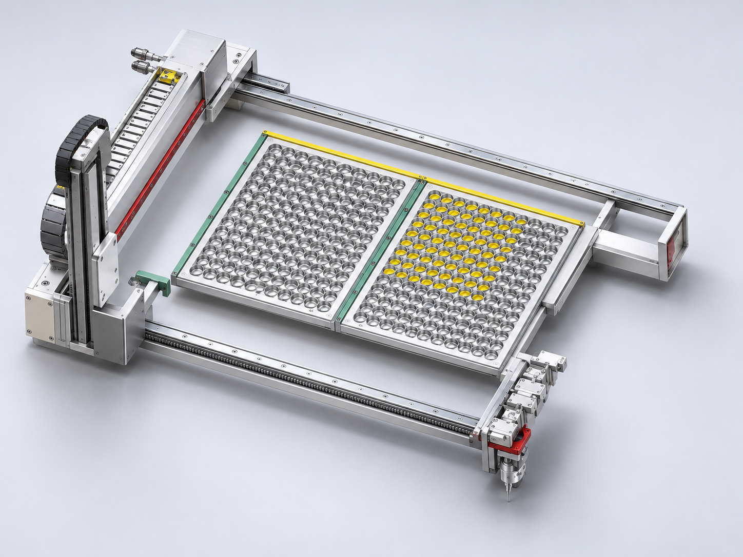
From the tray to the machine.
Where does the part sit in the tray? How is it picked up, and where does the machine receive it? These details define the loading and unloading sequence.
- Tray layout and how each part is held
- Handoff position at the existing machine
Check which side of the lens faces up.
Lens geometry and surface condition determine how its orientation can be checked. We consider where that check belongs in the transfer sequence.
- Lens shape and surface condition
- How the check fits into the transfer sequence
Keep the controls and service points within reach.
We review the control panel position, the clearance needed to open covers and the route to service points before adding automation.
- Operating position and clearance around the panel
- Access for adjustment and replacement
Define the retrofit
with maintenance in mind.
Machining quality, cycle time, floor space and maintenance access all affect whether a retrofit will work in daily use.
- Machining functions and available interfaces on the existing equipment
- How the part is held, where it is contacted and how quality will be checked
- Clearance to open covers, inspect components and replace parts
Start with a drawing or a process question.
Tell us about the part or machine, how it works today and what you want to change. You can get in touch before the specification is final.